Physical Processes in Non-Uniform Finite Magnetospheric Systems—50 Years of Tamao's Resonant Mode Coupling Theory
- Article
- Open access
- Published:
Hodograph method to estimate the latitudinal profile of the field-line resonance frequency using the data from two ground magnetometers
Earth, Planets and Space volume 65, pages 435–446 (2013)
Abstract
The hodograph method enables estimating the latitudinal profile of the field-line resonance (FLR) frequency (f R ) using the data from two ground magnetometers. This paper provides the full details of this method for the first time, and uses a latitudinal chain of ground magnetometers to examine its validity and usefulness. The hodograph method merges the widely-used amplitude-ratio and cross-phase methods in a sense that the hodograph method uses both the amplitude ratio and the phase difference in a unified manner; further than that, the hodograph method provides f R at any latitude near those of the two ground magnetometers. It is accomplished by (1) making a complex number by using the amplitude ratio (phase difference) as its real (imaginary) part; (2) drawing thus obtained complex numbers (one number for one frequency) in the complex plane to make a hodograph; and (3) fitting to thus obtained hodograph a model satisfying the FLR condition, which is a circle with the assumption that the resonance width is independent of the latitude. To examine the validity and usefulness of the hodograph method, we apply it to a Pc 4 event observed by the Scandinavian BEAR array. We also apply the amplitude-phase gradient method (Pilipenko and Fedorov, 1994; Kawano et al., 2002) to the same event, and compare the results; this is the first article applying the both methods to the same dataset.
1. Introduction
The field-line resonance (FLR) is the mechanism in which fast-mode (compressional) magnetosonic waves, propagating from the magnetopause into the inhomogeneous magnetosphere, excite the Alfven-mode waves via the resonant mode conversion. This is one of the key physics of ULF waves in the terrestrial magnetosphere. According to the theoretical concept of the FLR by Tamao (1965), the mode conversion is the most effective where the frequency of the incoming fast-mode waves matches the local frequency of the Alfvenic field-line oscillations (called the FLR frequency (fR) below). The growth of thus generated field-line oscillations is terminated at a certain level depending on the dominant dissipation mechanism, from which we can obtain the effective Q-factor of the FLR.
Southwood (1974) and Chen and Hasegawa (1974) formulated the FLR within the framework of a simplified model: a “plasma box” with 1D inhomogeneity across straight field lines. Despite the apparent simplicity of such a model, the spectral properties of the relevant system of MHD equations turned out to be useful in explaining observations. Following their work, the formulation was generalized for more complicated systems: multi-dimensional inhomogeneity, curvilinear magnetic field, finite plasma pressure and finite conductivity plasma boundaries; the results of these studies confirmed that the basic predictions of the 1D theory remain valid in a more realistic situation.
Ground magnetometer data include FLR signatures (in the ULF range), characterized by key parameters such as the FLR frequency fR and the resonance width δ which is an indicator of the damping scale of the resonance. Since fR is related to the magnetic field strength and the plasma density along the field line, we can use fR to diagnose the magnetospheric plasma density from the ground.
However, in actually observed ground magnetometer data, FLR-generated ULF waves are often difficult to identify due to superposed non-FLR signals (mainly compressional-type). To overcome this problem, the amplitude-ratio method (Baransky et al., 1985; Kurchashov et al., 1987; Gugliel’mi, 1989) and the cross-phase method (Waters et al., 1991), using ground magnetometer data from two stations separated by 50~250 km along a geomagnetic meridian, have turned out to be the most effective. These methods utilize the characteristic feature of FLR-generated ULF waves: Since the amplitude and phase of FLR-generated ULF waves sharply changes across the resonance latitude while the superposed signals are more global and almost the same at the two stations, taking the difference of the data from the two adjacent stations can cancel out the most of the non-FLR signals and extract even weak FLR signals. These methods have been applied to Pc3–4 pulsation data from two ground stations in middle to low latitudes, and the FLR parameters at a point (usually regarded as the midpoint) between the two stations have been successfully obtained (e.g., Baransky et al., 1985, 1989; Kurchashov et al., 1987; Green et al., 1993; Waters et al., 1994; Russell et al., 1999; Chi et al., 2000; Menk et al., 2000).
As stated above, the standard amplitude-ratio (cross-phase) method uses only the amplitude ratio (phase difference) between two stations to determine the FLR frequency. A problem here is that the two methods can provide different values of the FLR frequency.
As a countermeasure against this problem, the hodograph method, originally suggested by Kurchashov and Pilipenko (1996) and used in this paper, employs both the amplitude and phase information at the same time. Furthermore, the hodograph method allows to determine fR not only at the midpoint between the two stations but at (theoretically) any latitude; differently put, fR is obtained as a function of latitude or L (fR(L)). The details of the method will be presented in the next section.
Although the hodograph method has been applied to the study of some specific ULF events (Pilipenko and Kurchashov, 2000; Vellante et al., 2002), there is still no comprehensible description of this method widely available to the geophysical community. This is the first paper providing the full details of the hodograph method. We also note that the procedure No. 1–6 shown in Section 3, and its illustration Fig. 3 (explained below), are new, not used or shown in any previous papers. For the illustration of the hodograph method, we newly apply the method to the magnetometer data from the Scandinavian BEAR array (Korja, 1998). There we apply the hodograph method to a station pair and obtain fR as a function of latitude, and compare it with the results of applying the standard amplitude-ratio and cross-phase methods at different station pairs. Then we go further, apply the hodograph method to an adjacent station pair, and compare the results. Furthermore, in this paper we apply the “amplitude-phase gradient method” (APGM below) (Pilipenko and Fedorov, 1994; Kawano et al., 2002) (Section 5); this is the first time in literature that the hodograph method and the APGM are applied to the same dataset. We note here that APGM is different from the hodograph method: They are based on the same equation Eq. (1) (of this paper), but APGM does not have the concept of signal-noise separation but assumes that the obtained amplitude-ratio and cross-phase data include only an FLR signal and nothing else. The line-fitting procedure included in the hodograph method only enables the signal-noise separation. More details, including the drawback (i.e., assumption of a constant resonance width) of the hodograph method, will be explained below.

Illustrates the ζ (dimensionless latitudinal distance) profiles of the amplitude and phase of the magnetic field Fourier component Hm, caused by the field line resonance (FLR), as expressed by Eq. (1). The model parameters hR is set to 1. See text for more details.

Illustrates the model hodograph R m (Eq. (5)) based on the FLR theory, plotted on the complex plane. The hodograph, with the assumption that the resonance width δ is a constant, is a circle. See text for more details.

Illustrates the model hodograph R mm (Eq. (25)) modified from R m of Fig. 2 under the effect of the inhomogeneous underground conductivity. With the assumption that underground effect changes the amplitude ratio by a constant factor, and changes the cross phase by a constant number, the circle is rotated and dilated/contracted. See Section 3 for more details.
2. Methodology of the Hodograph Method
2.1 Overview
It is well known that the east-west component of the magnetic-field perturbation in space (associated with the radial electric field perturbation) caused by the FLR follows the equation of Southwood (1974) and Chen and Hasegawa (1974). On the ground, it is observed as the northward (H) component magnetic field perturbation, because the magnetic field perturbation caused by the ionospheric Hall (Pedersen) current is observed (neglibly small) on the ground (e.g., Hughes and Southwood, 1976) and because the electric field mapped from space to the ionosphere is north-south directed.
As shown by Pilipenko (1990), Pilipenko and Fedorov (1994), and Pilipenko et al. (2000) (see also references therein), the solution to the above equation can be asymptotically decomposed, and its leading term is expressed as follows (its valid range will be discussed later in the main text and in Appendix A):


with

where x is the ground position (latitude), f is the frequency, H m (x, f) is the Fourier component of the ground H component (the subscript m indicates that this is a theoretical model), x R (f) is the position (latitude) of the resonance point, δ is the resonance width, h R (f) is the amplitude at the resonance point, and ζ is the dimensionless distance of x from x R .
Since x refers to the ground latitude here, when it is field-aligned mapped to the geomagnetic equator in space, it increases with increasing distance from the Earth. We note here that Pilipenko and Kurchashov (2000) used the opposite increasing direction of x.
Figure 1 shows the amplitude (top) and phase (bottom) parts of Eq. (3) as a function of ζ for the case of h
R
= 1. The typical FLR pattern (amplitude peak and sharp phase change at the resonance point, i.e., at ζ = 0) is seen in this figure. The top panel also shows that the amplitude at ζ = ±1 (i.e., at x = x
R
± δ) is  times the peak amplitude, so that the wave power is half.
As a detail of the resonance width δ, or differently put the damping scale of the resonance, it is related to the damping rate in a system χ, which is the imaginary part of the complex frequency ω + iχ, as follows: δ = −(χ/2π)(∂f R (x)/∂x)−1 (e.g., Menk et al., 1994; Pilipenko and Fedorov, 1994; Waters et al., 1994). The sign of the gradient of f R (x), and correspondingly δ, determines the direction of an apparent phase velocity in the resonant region. Throughout the magnetosphere, except for the narrow region near the plasmapause (Dent et al., 2003) and the region very close to the Earth where the mass loading effect is significant (Menk et al., 2000; Kawano et al., 2002), f R (x) decreases with increasing x, and thus the meridional component of the apparent phase velocity is directed toward higher latitudes.
Now we return to the hodograph method itself. It is based on Eq. (1). In the method, we divide the model Eq. (1) for a station by the same model but for another station, as follows:


where

is the latitude of the midpoint between the two stations,

is the distance between the two stations (x1 > x2 is assumed here),

is the dimensionless resonance latitude (offset to zero at x0), and

is the dimensionless resonance width.
X(f) can be regarded as a value of the dimensionless coordinate

at f, where x (referring to the latitude in general) is equal to x R (f). It is to be noted that X = 0 at x = x0, X = 1 at x = x1, and X = −1 at x = x2.
If δ is a constant (which means that D is a constant), and if we regard Eq. (9) as a special case of complex transformation from complex variables X to R in which we only use the real axis in the X complex plane (because X(f) is a real number), then Eq. (9) has the form of a Mebius transformation (fractional-linear transformation); in this transformation, it is known that a line is transformed into a circle. With Eq. (9), the real axis in the complex X plane is transformed into a circle having the radius a which satisfies the equation

and having the center at

(a straightforward verification of this is given in Appendix B). This hodograph is illustrated in Fig. 2.
2.2 Key features of the hodograph
Here we summarize the important features of the above-explained (model) hodograph, as follows.
-
The hodograph is tangent to the real axis at 1 in the asymptotic limit of X(f) → ±∞. That is,
 (17)
(17) -
From the radius of the hodograph a, one can obtain the resonance width δ with the following equation:
 (18)
(18)


2.3 How to fit the hodograph to observed data
As stated above, the model hodograph (Eq. (9)) is a circle. On the other hand, one can also draw a data hodograph in the complex plane, as follows. One first calculates Ho,1(f) and Ho,2(f), Fourier Transform (FT) of the observed ground magnetic field H component at station #1 and #2. The Fast Fourier Transform (FFT) algorithm is widely used for its swiftness and convenience. (See Appendix C for another method using the cross-covariance function.) Thus obtained Ho,1(f) and Ho,2(f) are complex functions and include the amplitude and phase as follows:

where j = 1 or 2, A j (f) is the amplitude, and ψ j ( f ) is the phase. Then, for all f values of the FT’ed data, one can calculate the observation-based R, R o ( f ), with

One can plot thus obtained R o ( f ) in the complex plane for all the f’s to make a data hodograph.
It is to be noted here that, since

R o ( f ) includes both the amplitude ratio

and the cross phase

and merges the two in a natural way.
Having plotted R o (f) on the complex plane, the next step is to best-fit the model hodograph R m (f) of Eq. (9), i.e., a circle, to the data hodograph of R o (f). It is to be noted here that this model-fitting process means the signal-noise separation in the data (R o (f)): Here the signal is estimated by R m (f), and the difference from R m (f) to R o (f) refers to the noise. Then, from thus best-fitted model hodograph, one can obtain the resonance width δ using Eq. (18).
Note here that, throughout this methodology description, we use the term “signal” to refer to the FLR signal, and “noise” to mainly refer to the non-FLR signal (white-noise component is expected to be small because we usually smooth the FFT results in the frequency domain). Why we use this terminology is because the term “signal-noise separation” is widely used and intuitive, and because we are interested in the FLR signal in this paper.
A question regarding the above-stated procedure is if the circle should be fitted to all the frequency range of R o (f), or to data points near R o (f R (x0)) (f R (x0) is estimated by using the standard amplitude-ratio or cross-phase methods). A point to note here is that, as f goes far from f R (x0), both the bias and the noise increase in R o (f); the bias increases because the model of Eq. (1) is an asymptotic approximation around f R (x0) (see Appendix A for its comparison with the exact solution to Southwood’s equation), so that it deviates from the true FLR solution far from f R (x0). The noise increases because the FLR amplitude decreases with increasing distance from the resonance point, which means the decrease in the signal/noise ratio as f goes away from f R (x0). Thus, it is not a good idea to fit the model hodograph R m (f) to all the frequency range of R o (f). On the other hand, selection of a too narrow frequency range near f R (x0) makes the above-stated signal-noise separation inefficient (as an extreme example, if we choose only three datapoints, a circle is perfectly fitted to these three datapoints, yielding zero noise term). A guideline for the selection is to first draw all the R o (f) data in the complex plane, and then to select the frequency range for which R o (f) looks circular. This selection has to be made by visual inspection, and thus the selection process is more-or-less case-by-case.
We note that Pilipenko and Fedorov (1994) suggested the inequity

to roughly identify the range of x for which Eq. (1) is close enough to the FLR field of Southwood and Chen and Hasegawa (see Appendix A for more details). In the following we will use this inequity to indicate the valid, or differently put, precise-enough frequency range of the hodograph-method results.
Another point to note in doing this model-circle fitting is that the model assumes a constant resonance width; thus, the data points can also shift from the circle where the resonance width systematically changes near the utilized ground station pair. One has to remember this point when using the hodograph method.
The next and important step is to estimate the FLR frequency f R as a function of latitude x. This is achieved by an inverse procedure, as follows. For any given f (denoted as f g here), R o (f g ) is already plotted on the complex plane, and the best-fitted model hodograph (circle) is also plotted; then, one can find R m (f g ), i.e., the corresponding point on the model hodograph closest to the R o (f g ), by simply drawing a line running through both the center of the model-hodograph circle and R o (f g ) and finding the point where this line intersects the model hodograph. Then, by inserting thus obtained R m (f g ) into Eq. (9), one obtains X(f g ), and by inputting thus obtained X(f g ) into Eq. (12), one obtains x R (f g ). After having finished obtaining x R (f) for all f’s, one can then inverse the x R (f) function to obtain f(x R ), which is the same as f R (x) in its meaning.
2.4 Advantages of the hodograph method
The hodograph method is improved over the standard amplitude-ratio method and the cross-phase method in the following aspects.
-
The amplitude-ratio method and the cross-phase method provide single frequencies, the obtained frequency includes the effects of both the FLR signal and non-FLR signals (which cannot be perfectly cancelled out by these methods) in the amplitude-ratio and cross-phase data, and there is no mathematically established procedure to estimate the error (i.e., the effect of the non-FLR signal) in the obtained frequency. On the other hand, the hodograph method best-fits a model hodograph to several data points (corresponding to several frequencies), thus can separate the FLR signal (i.e., the fitted hodograph) from non-FLR signals. (A caution here is that the model hodograph assumes a constant resonance width; thus, the data points can also shift from the model hodograph where the resonance width systematically changes near the utilized ground station pair. One has to remember this point when using the hodograph method.)
-
The obtained f R (x) (explained above) is a continuous function of latitude; that is, with the hodograph method, one can obtain the FLR frequency at (theoretically) any latitude by using the data from the two ground magnetometers. (In actuality, the accuracy of the solution decreases with increasing distance from the two stations, as stated above.)
3. Correction of the Influence of the Underground Conductivity
The above-stated model hodograph reaches R m (f) = 1 at f → ±∞, as stated above. However, in fact, it is possible that the observed R o does not approach R = 1 at f → ±∞ because of the difference between the two stations in the underground conductivity, which modifies the original signal and distorts the hodograph. (We note here that, for the standard amplitude-ratio and cross-phase methods, neglecting this effect can result in biases in the obtained f R at the midpoint between the two stations. We also note that the difference between the ionospheric conductivities above the two stations could also modify the original signal, but in this paper we are interested in the FLR signal, thus we simply call these non-FLR effects by the term “influence of the underground conductivity.”)
To correct for this effect, we use a procedure which is a generalization of the procedure of Green et al. (1993) (applied to the amplitude-ratio and cross-phase methods). That is, we assume that the underground effect changes the amplitude ratio by a constant factor, and changes the cross phase by a constant number, in the vicinity of the FLR frequency at x = x2 ~ x1. (In general, frequency dependence is likely to exist, but the current methodology of the hodograph method does not include it; it is a topic of future research to include it in the methodology. At least Pilipenko and Kurchashov (2000) and Vellante et al. (2002) applied the hodograph method (with the above assumption) to their observations and obtained reasonable results.)
Then, for the equation of the hodograph (Eq. (9)), the above effect can be expressed by multiplying to Eq. (9) a frequency-independent (i.e., constant) complex factor M, as follows:

where G m (f) is the theoretical amplitude ratio and Δψ m (f) is the theoretical cross phase (see Eqs. (5), (22) and (23)).
As a result of this modification, the model hodograph R m (Eq. (9)) is ǀMǀ-times expanded and rotated by arg(M) around the coordinate origin. However, the modified hodograph (referred to as R mm below) is still a circle.
The M which best-fits the observation can be obtained by using the following procedures. Readers are referred to Fig. 3 for the illustration.
-
1)
Best-fit a circle R mm to the data hodograph R o . Let us denote the center of the best-fitted circle as α + iβ and its radius as γ.
-
2)
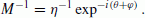
Calculate the modulus ξ and argument θ of the circle center by using the equations
 and
and  .
. -
3)
Draw a line (Line (3) below) from the coordinate origin to the circle center.
-
4)
Draw a line (Line (4) below) which starts from the coordinate origin and is tangent to the upper part of the circle. The modulus, η, of the tangent point satisfies the equation
 .
. -
5)
Calculate the angle φ from the Line (3) to Line (4), by using the equation
 (φ is always positive.)
 -
6)
Conversion from the fitted circle R mm (including the underground effect) to the model circle R m (from which the underground effect is removed) is accomplished by multiplying M−1 to R mm (see Eq. (25)). This conversion refers to the rotation (around the coordinate origin) of the fitted circle R mm by −(θ + φ) (note here that θ can be positive or negative according to its definition (2)), and dilation/contraction which moves η + i0 (the circle’s tangent point at the real axis after the rotation) to 1 + i0 (tangent point of R m ); see Eq. (17) and Fig. 2. Thus, M satisfies the following equation:
 (26)
(26)
 and
and  .
. .
. (φ is always positive.)
After M is thus determined, one can multiply M−1 to R mm to remove the underground effect, and the result is the R m in Section 2 (see also Eq. (25)). One can also multiply M−1 to the data hodograph R o (f) to remove the underground effect; in the following, we will refer to the result as R oc (f). After this underground-effect removal, the analysis procedure is the same as is described in Section 2. It deserves to note here that the radius of R m , a (Eq. (15)), satisfies the following equation.

4. Hodograph Analysis of a Pc 4 Event Observed by a BEAR Magnetometer Chain
As stated above, the hodograph method can yield the FLR frequency as a continuous function of latitude from only two (latitudinally-separated) ground magnetometers. To illustrate it, we use a chain of closely spaced four ground-magnetometer stations belonging to the BEAR array in northern Europe, which array was in operation for about one month in 1998 (Korja, 1998). Readers are also referred to Milling et al. (2001) for more details of BEAR. The magnetometers were fluxgate type, and recorded magnetic field variations with 2-sec sampling rate. The names of the selected stations are, from higher latitude, B28, B38, B37, and B36 (see Table 1). They cover the magnetic latitude range (in CGM coordinates) from 59.6° to 55.2° along the 105° magnetic meridian (longitudinal distances of the stations from the 105° meridian were less than 0.7°). This meridian crosses the MLT midnight at ~2120 UT every day. The latitudinal positions of the stations are shown in Table 1.
Table 1 also shows the dimensionless coordinate (latitude) X of the stations and the midpoints of adjacent stations, calculated by using Eq. (14) with x1 (x2) set to the CGM latitudes of B38 (B37). That is, we apply the hodograph method to the B38–B37 pair (more details are described just below).
In this section we apply the hodograph method to Pc 4 magnetic pulsations observed at 0750–0830 UT on Day 177 (June 26), 1998 and study the latitudinal profile of the FLR frequency. The H-component amplitude was significantly enhanced during this interval with the peak-to-peak amplitude of ~20 nT (not shown). We apply the hodograph method to the B38-B37 pair, while the standard two-station methods (amplitude-ratio and cross-phase methods) are applied to the other two pairs (B28-B38 and B37-B36), and the results are compared.
Figure 4 shows the amplitude ratio (top panel) and the cross phase (bottom panel) calculated from the B38-B37 pair. FFT was applied to all the 1200 data points in the interval 0750–0830 UT (since the sampling rate is 2 s, a 40-min interval includes 40 × 60/2 = 1200 data points). The resultant data points in the frequency domain are shown by asterisks in Fig. 4.

Shows the amplitude ratio and the cross phase calculated from the B38-B37 station pair’s data of Pc 4 magnetic pulsations observed at 0750–0830 UT on Day 177 (June 26), 1998. The two vertical dashed lines surround the frequency range where both the amplitude ratio and the cross phase smoothly change. See text for more details.
The two vertical dashed lines in Fig. 4 surround the frequency range in which the amplitude ratio shows a smooth bipolar pattern and the cross phase shows a smooth unipolar pattern: At the leftside dashed line the amplitude ratio shows a sudden change in its gradient, and at the rightside dashed line the cross phase starts to decrease again. That is, the frequency range between the two dashed lines are where an FLR signature is dominant. Thus, we apply the hodograph method to the data points between the two vertical dashed lines (there are 24 data points).
Figure 5 shows the results of applying the hodograph method to the above-explained data, as follows. From each data (asterisks) shown in Fig. 4, the complex ratio R o (f) is calculated (see Eq. (19) through Eq. (23)) and plotted in Fig. 5 as asterisks. The 24 data points corresponding to those between the two dashed lines in Fig. 4 are shown by superposed small circles; as stated above, to these asterisks-and-circle points the model hodograph circle R mm (f) (including the underground effect; see Eq. (25)) is best-fitted (procedure No. 1 in Section 3). (Here we note we have used the Taubin method (Taubin, 1991) to best-fit a circle; this method is known to be robust and accurate.) The best-fit circle is shown on the figure; its center is located at α + iβ = 1.010 − 0.491i, and its radius γ is 0.337. Then, by following the procedure No. 2 through No. 5 in Section 3, we obtain the following numbers for the other geometrical parameters illustrated in Fig. 5: ξ = 1.12, θ = −25.9°, η = 1.07, and φ = 17.5°.

Then, following the procedure No. 6 in Section 3, we obtain M−1 = 0.923 + 0.137i (Eq. (26)), and by multiplying it to R mm (f) and R o (f) (see Eq. (25)) we obtain quantities from which the underground effect has been removed: R m (f) (model complex ratio) and R oc (f) (observed complex ratio). Figure 6 shows the R m (f) (a large circle) and the R oc (f) (small circles, corresponding to the asterisk-and-circles in Fig. 5). We can see in Fig. 6 that, just as expected, R m (f) is tangent to the real axis at 1. The distance of the circle center from the real axis is equal to D−1 = 0.314 (see Eq. (27)), which means that the unnormalized resonance width δ is 1.66° in latitude (see Eq. (13) and Table 1).

Shows the result of removing the underground effect from the data shown in Fig. 5. The small-circle data points R oc correspond to the asterisk-and-circle data points in Fig. 5. See Section 3 for more details.
Figure 7 illustrates, for each data point having a specific frequency f i (i = 1…24, corresponding to the frequencies of the data points in Fg. 4 between the two vertical dashed lines), the relation between the observation R oc (f i ) (small circle, same as in Fig. 6) and the corresponding model-fitted value R m (f i ) (diamond); by definition of the fitting procedure, R m (f i ) (diamond) is a point where the line running through the center of the large circle and R oc (f i ) (small circle) crosses the large circle. The two short-dashed lines shown in Fig. 7 illustrates such relation between R oc (f i ) and R m (f i ). These 24 R m (f i )’s are used to calculate the latitudinal dependence of the FLR frequency, and the distance between R oc (f i ) and R m (f i ) in Fig. 7 refers to noise (to be more specific, non-FLR signals) in the observation R oc (f i ).

Similar to Fig. 6, but for each frequency f of FFT, illustrates the locations of the observed data point R oc (f) (small circles, the same as in Fig. 6) and the best-fitted model value R m (f) (diamonds). See text for more details.
Figure 8 shows the result of calculating the FLR latitude x R (f i ) from the above-obtained R m (f i ) by using Eq. (5) through Eq. (13) (tilted curve). Note that f i is shown in the vertical axis while x R (f i ) is shown in the horizontal axis: That is, the FLR frequency as a function of latitude, f R (x), is the inverse function of x R (f). Figure 8 also shows the latitudes of the stations B28, B38, B37, and B36 by vertical dashed lines.

The slanted line shows the result of estimating the latitudinal distribution of the FLR frequency f R (x) (or x R (f) before the interchange of the horizontal and vertical axes), calculated from R m (f) in Fig. 7 (diamonds) by using Eq. (5) through Eq. (13). In general, the reliability of f R (x) obtained with the hodograph method tends to decrease with increasing distance from the midpoint between the two stations used; the solid-line part corresponds to the valid, or differently put, precise-enough range of the hodograph method calculated by using Eq. (24). Squares (circles) show the results of applying the amplitude-ratio (cross-phase) method to all the adjacent station pairs. Locations of all the stations are shown by vertical dashed lines. See text for more details.
In Fig. 8, the solid-line part of the f R (x) curve corresponds to the valid range calculated by using Eq. (24). We can see that the valid range is centered around the midpoint of B38 and B37 (their data were used for the calculation), and that the valid range is about three times wider than the distance between the two stations (B38 and B37) used for the calculation.
Figure 8 also shows the results of applying the amplitude-ratio method (squares) and the cross-phase method (open circles) to each adjacent two stations. In the amplitude ratio method, we have determined the FLR frequency as the average of the frequencies where the amplitude ratio becomes maximum and minimum. In the cross-phase method, we have determined the FLR frequency as that where the cross phase has the peak. As the error bar of the cross-phase FLR frequency, we have used the half width of the cross-phase profile; this could be an overestimate, but there is no mathematically established procedure to estimate the confidence interval of the cross-phase FLR frequency. As the error bar of the amplitude-ratio FLR frequency, we have used the half of the frequency difference between the two peak frequencies of the amplitude ratio. Figure 8 shows the above-stated error bars, and we can see that the lengths of the two error bars are not very different, and that the error bars for the three station pairs touches the f R (x) curve (the B37-B36 pair’s error bars barely miss the curve.)
5. Discussion and Summary
This paper has provided full details of the hodograph method (Kurchashov and Pilipenko, 1996) for the first time with new intuitive ways (i.e., procedure No. 1–6 in Section 3, with its illustration in Fig. 3) to explain the methodology. This paper has also illustrated the actual application procedures by using a new example dataset from the Scandinavian BEAR array (Korja, 1998). The hodograph method uses the ground magnetometer H-component data from two adjacent stations, like the widely-used amplitude-ratio method (Baransky et al., 1985) and cross-phase method (Waters et al., 1991). However, the hodograph method differs from the other two methods in the following aspects:
-
1)
The hodograph method merges the amplitude-ratio method and cross-phase method in a natural manner and provides a single value of the FLR frequency (f R ) at the midpoint between the two stations (Fig. 8). (The amplitude-ratio or the cross-phase methods by themselves give respectively just a single value of f R , but it often happens that the two f R ’s are fairly different.)
-
2)
While the cross-phase method and the amplitude-ratio method provide f R ’s only at the midpoint between the two stations, the hodograph method provides f R as a continuous function of latitude x, i.e., f R (x), by using the same data from the two stations only (Fig. 8).
-
3)
The hodograph method can make a signal-noise separation of the data in a systematic manner, in terms of model fitting and residual (Fig. 7). (To be more specific, the term “signal” here refers to the FLR signal, to which we are interested, while the term “noise” here mainly refers to non-FLR signals. A point to note here is that the model hodograph assumes a constant resonance width; thus, the data points can also shift from the model hodograph where the resonance width systematically changes near the utilized ground station pair.)
-
4)
The hodograph method includes the procedure to correct the effects of the inhomogeneous underground crust conductivity (Section 3).
The essence of the hodograph method (leading to the above features) is, for each frequency f of the FFT’ed H-component data, to make a complex-number ratio R o (f) between the two stations’ data (including both the amplitude ratio and the phase difference; see Eq. (20)), to plot thus obtained R o (f)’s on the complex plane, and to best-fit to them a model hodograph R m (f) (Eq. (5)) which conforms to the FLR theory (Eq. (1)).
As an illustration of the hodograph method application, we have used the ground-magnetometer data from a BEAR station chain along the 105° meridian (from higher latitude, B28, B38, B37, and B36 (see Table 1)). That is, we (a) applied the standard amplitude-ratio method and cross-phase method to the B28-B38, B38-B37, and B37-B36 pairs, (b) applied the hodograph method to the B38-B37 pair, and compared the results of (a) and (b). We note that this kind of comparison has been made for the first time in literature.
As a result of the comparison of (a) and (b), Fig. 8 shows that, taking into account the estimation errors in the amplitude-ratio method and the cross-phase method, the f R (x) profile obtained from the B38-B37 pair provides fairly good estimate of f R at the midpoints of B28-B38 and B37-B36, even though the both midpoints are located outside the latitudes covered by the B38-B37 pair.
Still, if one draws a best-fit line to the cross-phase FLR and amplitude-ratio FLR data (six in total) shown in Fig. 8, the six points are fairly aligned to that line, and that line makes a finite angle to the above-obtained curve of f R (x). This is of some concern, so here we apply the hodograph method to another pair (i.e., B28-B38) and see the result, as follows.
Figure 9 shows the amplitude-ratio and the cross-phase data for all the three station pairs. The vertical dashed lines show the range in which the FLR pattern (i.e., a bipolar pattern in the amplitude ratio plus a unipolar pattern in the cross phase) is visually identified.

Shows the amplitude ratio and the cross phase calculated from the B28-B38 (top), B38-B37 (middle), and B37-B36 (bottom) ground station pairs. Each pair has two panels: The amplitude ratio (upper) and the cross phase (lower). Vertical dashed lines surround the frequency range where the amplitude ratio (cross phase) shows a bipolar (unipolar) pattern. See text for more details.
Figure 10 shows the hodograph made from the B37-B36 data shown in the bottom two panels of Fig. 9 (between the two vertical dashed lines). The result of circle-fitting to these data are also shown. The data hodograph is too far away from a simple circular shape to make us think it meaningful to calculate f R (x) using the hodograph method.

Shows the hodograph for the B37-B36 pair. The datapoints (small open circles) correspond to the B37-B36 data (asterisks) in the bottom two panels of Fig. 9 between the two vertical dashed lines. The data hodograph is too far away from a simple circular shape to make it meaningful enough to calculate f R (x) using the hodograph method.
On the other hand, the hodograph made from the B28-B38 data shown in the top two panels of Fig. 9 looked circular enough (not shown), so we have applied the hodograph method to the data. The result is superposed on Fig. 8 to make Fig. 11. This figure shows that the B28-B38 f R curve never crosses with the B38-B37 f R curve, which is not a good sign, even though the valid ranges of the f R curves (i.e., the two solid-line segments) are overlapped by the vertical error bars of the amplitude-ratio and cross-phase methods.

The same as Fig. 8 except that the result of applying the hodograph method to the B28-B38 pair is superposed. See text for details.
To think about the reason of this separation of the two curves, we have applied APGM (Pilipenko and Fedorov, 1994; Kawano et al., 2002) to the raw data of the amplitude ratio and the cross phase, and the result is shown in Fig. 12. We note here that we did not use the data after the removal of the underground effect by the hodograph method (such as are shown in Fig. 6) but used the raw data as shown in Fig. 9: We did so on purpose here, as explained below. The standard APGM includes the preprocessing of removing the underground effect (Kawano et al., 2002).

(Top) Shows the the FLR frequency f R (x) obtained by applying the amplitude-phase gradient method (APGM) (Pilipenko and Fedorov, 1994; Kawano et al., 2002) to the “raw” data of the amplitude ratio and the cross phase calculated from the same data as those used in Fig. 11; the word “raw” here means that APGM was applied to the amplitude ratio and cross phase including the underground-origin component. We did so on purpose here, and the standard APGM includes the preprocessing of removing the underground-origin component (Kawano et al., 2002). See text for more details. (Bottom) Shows, just for information, the resonance width δ(x) obtained at the same time as the above f R (x) as a result of applying the APGM. Note that the sharp gradient at the edges, etc. are not real but the result of not removing the underground effect.
The top panel of Fig. 12 shows f R (x)’s from the two station pairs; the slopes of the two curves are now steeper, and the two curves crosses with each other, which is a good sign. On the other hand, the resonance widths calculated with APGM, shown in the bottom panel of Fig. 12, show sharp enhancement near the edges, which is probably unrealistic.
What we can deduce from the comparison between Fig. 11 and Fig. 12 is that, for the event analyzed in Section 4, the most realistic values of the underground-origin component exist somewhere between zero (resulting in Fig. 12) and those obtained by the hodograph method (resulting in Fig. 11); the hodograph method subtracted too much for the event of Section 4.
A possible cause of this too much subtraction is that the amplitude ratio and the cross phase of the event in Section 4 did not have an asymptotic flat part: For example for the event of Kawano et al. (2002), their figure 4 shows flat parts of the amplitude ratio (cross phase) at the edges of its bipolar (unipolar) part. With the asymptotic flat part, we can obtain an idea on the order of the underground effect before applying the hodograph method.
On the other hand for the event in Section 4 of this paper, Fig. 9 shows that the bipolar (unipolar) part of the amplitude ratio (cross phase) is not surrounded by such asymptotic flat parts. It could mean that the adjacent parts, having different frequency dependence, comes from different sources, and the different sources are in fact affecting the bipolar/unipolar part and deforming its waveform. (It could also bias the results of the amplitude-ratio method and the cross-phase method.) A lesson from the data-analysis part of this paper would be: “Avoid events whose amplitude ratio and cross phase do not show a gradual shift toward asymptotic flat parts.”
As long as we avoid such events, we believe the hodograph method is a useful method, as summarized as four items at the beginning of this section; it is a topic of future research to do the same analysis as this paper for another event having the amplitude ratio and the cross phase whose edges are flat. Another topic of future research is to improve the hodograph method so that it enables a flexible latitude dependence of δ(x).
References
Baransky, L. N., J. E. Borovkov, M. B. Gokhberg, S. M. Krylov, and V. A. Troitskaya, High resolution method of direct measurement of the magnetic field line’s eigen frequencies, Planet. Space Sci., 33, 1369, 1985.
Baransky, L. N., S. P. Belokris, Yu. E. Borovkov, M. B. Gokhberg, E. N. Fedorov, and C. A. Gree, Restoration of the meridional structure of geomagnetic pulsation fields from gradient measurements, Planet. Space Sci., 37, 859–864, 1989.
Chen, L. and A. Hasegawa, A theory of long-period magnetic pulsations, 1, Steady state excitation of field line resonance, J. Geophys. Res., 79, 1024–1032, 1974.
Chi, P. J., C. T. Russell, S. Musman, W. K. Peterson, G. Le, V. Angelopoulos, G. D. Reeves, M. B. Moldwin, and F. K. Chun, Plasmaspheric depletion and refilling associated with the September 25, 1998 magnetic storm observed by ground magnetometers at L = 2, Geophys. Res. Lett., 27, 633–636, 2000.
Dent, Z. C., I. R. Mann, F. W. Menk, J. Goldstein, C. R. Wilford, M. A. Clilverd, and L. G. Ozeke, A coordinated ground-based and IMAGE satellite study of quiet-time plasmaspheric density profiles, Geophys. Res. Lett., 30, 1600, doi:10.1029/2003GL016946, 2003.
Green, A. W., E. W. Worthington, L. N. Baransky, E. N. Fedorov, N. A. Kurneva, V. A. Pilipenko, A. A. Bektemirov, and E. Philipov, Alfven field line resonances at low latitude (L=1,5), J. Geophys. Res., 98, 15693–15699, 1993.
Gugliel’mi, A. V., Diagnostics of the plasma in the magnetosphere by means of measurement of spectrum of Alfven oscillations, Planet. Space Sci., 37, 1011–1012, 1989.
Hughes, W. J. and D. J. Southwood, The screening of micropulsation signals by the atmosphere and ionosphere, J. Geophys. Res., 81, doi:10.1029/JA081i019p03234, 1976.
Kawano, H., K. Yumoto, V. A. Pilipenko, Y.-M. Tanaka, S. Takasaki, M. Iizima, and M. Seto, Restoration of continuous field line eigenfrequency distribution from ground-based ULF observations, J. Geophys. Res., 107, doi:10.1029/2001JA000274, 2002.
Korja, T., BEAR—Baltic Electromagnetic Array Research, EUROPROBE News, pp. 4–5, 12, 1998.
Kurchashov, Yu. P. and V. A. Pilipenko, Geometrical method for the analysis of the ULF gradient observation data, Geomagn. Aeron., 36, 53–60, 1996.
Kurchashov, Yu. P., Ia. S. Nikomarov, V. A. Pilipenko, and A. Best, Field line resonance effects in local meridional structure of mid-latitude geomagnetic pulsations, Ann. Geophys., 5, 147–154, 1987.
Menk, F. W., B. J. Fraser, C. L. Waters, C. W. S. Ziesolleck, Q. Feng, S. H. Lee, and P. W. McNabb, Ground measurements of low latitude magnetospheric field line resonances, in Solar Wind Sources of Magnetospheric Ultra-Low-Frequency Waves, Geophysical Monograph 81, edited by M. J. Engebretson, K. Takahashi and M. Scholer, p. 299, 1994.
Menk, F. W., C. L. Waters, and B. J. Fraser, Field line resonances and waveguide modes at low latitudes 1. Observations, J. Geophys. Res., 105,7747–7761, doi:10.1029/1999JA900268, 2000.
Milling, D. K., I. R. Mann, and F W. Menk, Diagnosing the plasmapause with a network of closely spaced ground-based magnetometers, Geophys. Res. Lett., 28, 115–118, doi:10.1029/2000GL011935, 2001.
Pilipenko, V. A., ULF waves on the ground and in space, J. Atmos. Terr. Phys., 52, 1193–1209, 1990.
Pilipenko, V. A. and E. N. Fedorov, Magnetotelluric sounding of the crust and hydrodynamic monitoring of the magnetosphere with the use of ULF waves, in Solar Wind Sources of Magnetospheric Ultra-Low-Frequency Waves, Geophysical Monograph 81, edited by M. J. Engebretson, K. Takahashi and M. Scholer, p. 283, 1994.
Pilipenko, V. A. and Yu. P. Kurchashov, A hodograph method of analysis for geomagnetic pulsation observations, Int. J. Geomagn. Aeron., 2, 87–92, 2000.
Pilipenko, V., M. Vellante, and E. Fedorov, Distortion of the ULF wave spatial structure upon transmission through the ionosphere, J. Geophys. Res., 105, 21225–21236, 2000.
Russell, C. T., P. J. Chi, V. Angelopoulos, W. Goedecke, F K. Chun, G. Le, M. B. Moldwin, and G. D. Reeves, Comparison of three techniques for locating a resonating magnetic field line, J. Atmos. Terr. Phys., 61, 1289–1297, 1999.
Southwood, D. J., Some features of field line resonances in the magnetosphere, Planet. Space Sci., 22, 483–491, 1974.
Tamao, T., Transmission and coupling resonance of hydromagnetic disturbances in the non-uniform Earth’s magnetosphere, Sci. Rep. Tohoku Univ. Ser. 5, Geophys., 17, 43–72, 1965.
Taubin, G., Estimation of planar curves, surfaces and nonplanar space curves defined by implicit equations, with applications to edge and range image segmentation, IEEE Trans. PAMI, 13, 1115–1138, doi:10.1109/34.103273, 1991.
Vellante, M., M. De Lauretis, M. Forster, S. Lepidi, B. Zieger, U. Villante, V. A. Pilipenko, and B. Zolesi, Geomagnetic field line resonances at low latitudes: Pulsation event study of 16 August 1993, J. Geophys. Res., 107, 1060, doi:10.1029/2001JA900123, 2002.
Waters, C. L., F. W. Menk, and B. J. Fraser, The resonance structure of low latitude Pc3 geomagnetic pulsations, Geophys. Res. Lett., 18,2293–2296, doi:10.1029/91GL02550, 1991.
Waters, C. L., F. W. Menk, and B. J. Fraser, Low latitude geomagnetic field line resonance: Experiment and modeling, J. Geophys. Res., 99, 17547–17558, doi:10.1029/94JA00252, 1994.
Acknowledgments
The authors would like to thank the SVEKALAPKO BEAR Working Group, Toivo Korja from the University of Oulu, Finland, and David Milling from the University of Alberta, Canada for the availability of the BEAR data. The research of V.A.P. is partly supported by the Program 22 of Russian Academy of Sciences. This research was also made possible in part by the fellowship to V.A.P. from Nagoya University. The research of H.K. is partly supported by a research program of the International Center for Space Weather Science and Education, Kyushu University. Calculations of the geomagnetic coordinates were made at http://nssdc.gsfc.nasa.gov/space/cgm/cgm.html. A matlab function to realize the Taubin method, CircleFitBy-Taubin.m (written by N. Chernov) was obtained through the “matlab central” website http://www.mathworks.co.jp/matlabcentral.
Author information
Authors and Affiliations
Corresponding author
Appendices
Appendix A. Valid Range of Eq. (1)
Here we compare the approximate solution to the FLR-generated ground H-component field Eq. (1) with more precise solution. As the latter, we refer to Eq. (5) of Southwood (1974), i.e.,

where x is the radial coordinate in space, E(x) is the electric field, x R (x0 in the original paper) is the resonance point, δ (ϵ in the original paper) corresponds to the resonance width of Eq. (1), and λ is the toroidal wavenumber. We note this is also an approximate equation by inputting into the general FLR equation (their Eq. (2)) a linear x profile of {V A (x)}−2 (where V A refers to the Alfven velocity)) and a straight magnetic field in the z direction; but its solution, shown just below, is still more precise than Eq. (1).
Equation (A.1) has a solution

where D is a constant and K0 is the zeroth-order modified Bessel function. (We ignore I0 here for simplicity and because it becomes minimum at the resonance point.)
The ground H is generated by E
x
(more precisely, by the ionospheric Hall current generated by E
x
), thus what we actually need is E
x
; Eq. (1) of Southwood shows it is proportional to  , thus we can write

where D′ is a constant and K1 is the first-order modified Bessel function.
Figure A.1 compares Eq. (1) of this paper with the above-stated more precise solution Eq. (A.3) in the same format as Fig. 1. The maximum amplitude is set to one, x R = 0, and δ = 0.5 for the both curves, and the horizontal axis is normalized to ζ (Eq. (4)), to make it easy to compare this figure with Fig. 1. λ = 1/5 is arbitrarily chosen. In the top panel, one can see that, as the observer’s latitude x moves away from the FLR latitude x R , Eq. (1) gradually deviates away from Eq. (A.3).

Shows a solution for the FLR equation by Southwood (1974) (dashed line) and Eq. (1) in the same format as Fig. 1. The vertical dashed lines corresponds to the valid, or differently put, precise-enough range of Eq. (1), given by Eq. (24). See text for more details.
Pilipenko and Fedorov (1994) suggested the inequity

to roughly identify the range of x for which Eq. (1) is close enough to the FLR field of Southwood and Chen and Hasegawa. This range is shown in the figure by the vertical dashed lines.
In the top panel of Fig. A.1, the relative amplitude difference between the two curves (difference divided by Southwood’s solution) in this range is only 3.8% at maximum.
The bottom panel of Fig. A.1 shows the phases; in the frequency range surrounded by the two vertical dashed lines, the phase difference between the two curves is small (1.5 ~ 4.2°). In addition, the two curves are mostly parallel to each other (with the distance changing by only 2.7° while each phase changes by ~90°), thus the phase-difference profile between two stations’ data are little affected by the difference shown in the bottom panel.
With the above two results for the amplitude and phase, we can say that the inequality (24) points to the valid, or differently put, precise-enough range of Eq. (1).
Appendix B. Verification of the Complex Transformation
Here we verify that, with Eq. (9), the real axis in the X complex plane (because X(f) is in fact a real number) makes a circle in the R complex plane. First we write R = u + iv where u(v) refers to the real (imaginary) part of R. Then, from Eq. (9),

thus

Then, by equating the real part and the imaginary part, we obtain u(X − 1)− vD = X + 1 and v(X − 1) + uD = D. Then, from the real part we obtain  and from the imaginary part we obtain
  . Thus,
  , and from this we obtain, after some algebra,

Thus, as X(f) moves on the real axis of the X complex plane, the corresponding trace (=hodograph) in the R complex plane becomes a circle of radius D−1 having its center at 1 − iD−1.
Appendix C. Calculation of the Amplitude-ratio and the Cross-phase from the Cross-covariance Function
Instead of first calculating FFT of the observed data, one may first calculate the auto-covariance functions and the cross-covariance function

where j = 1 or 2, h j (n) is the H-component data at station j, n is the data number (referring to time), k is the lag number (referring to the time difference), N is the number of data, and μ j is the average of h j .
One then calculates FFT of C ij (k) as S ij (f), and from thus obtained S ij (f), one can calculate the amplitude-ratio G(f) and the cross-phase Δψ(f) with the following equations, as shown by Vellante et al. (2002):

if the signal/noise ratio is the same at the two sites, or

with

if the noise level is the same at the two sites; and

The results of using Eq. (C.2) and Eq. (C.5) are identical to the results of using Eq. (22) and Eq. (23) (i.e., calculations starting with FFT of h j (n)). That is, when one uses Eq. (22) and Eq. (23), one is implicitly assuming that the signal/noise ratio is the same in the two datasets; as long as one assumes so, the calculation using Eq. (22) and Eq. (23) is much faster than using Eq. (C.2) and Eq. (C.5), because the calculation of C jk (k) (Eq. (C.1)) requires operations in the order of N2 while FFT requires much smaller number of operations.
Rights and permissions
Open Access This article is licensed under a Creative Commons Attribution 4.0 International License, which permits use, sharing, adaptation, distribution and reproduction in any medium or format, as long as you give appropriate credit to the original author(s) and the source, provide a link to the Creative Commons licence, and indicate if changes were made.
The images or other third party material in this article are included in the article’s Creative Commons licence, unless indicated otherwise in a credit line to the material. If material is not included in the article’s Creative Commons licence and your intended use is not permitted by statutory regulation or exceeds the permitted use, you will need to obtain permission directly from the copyright holder.
To view a copy of this licence, visit https://creativecommons.org/licenses/by/4.0/.
About this article
Cite this article
Pilipenko, V.A., Kawano, H. & Mann, I.R. Hodograph method to estimate the latitudinal profile of the field-line resonance frequency using the data from two ground magnetometers. Earth Planet Sp 65, 435–446 (2013). https://doi.org/10.5047/eps.2013.02.007
Received:
Revised:
Accepted:
Published:
Issue Date:
DOI: https://doi.org/10.5047/eps.2013.02.007